Gallery > Galleries helicopters/engines
Gallery engines (single-cylinder, boxer- and V-engines)
Below are photos of model engines (single-cylinder, boxer and V-engines) and the CNC milling machines that were created according to the construction plans of CAD+Modelltechnik Jung.
Many thanks to all senders of the photos!
If you as a customer of "CAD+Modelltechnik Jung" would also like to present photos of your manufactured engine or the CNC milling machine here, then send us an email to: cad-modelltechnik-jung@web.de
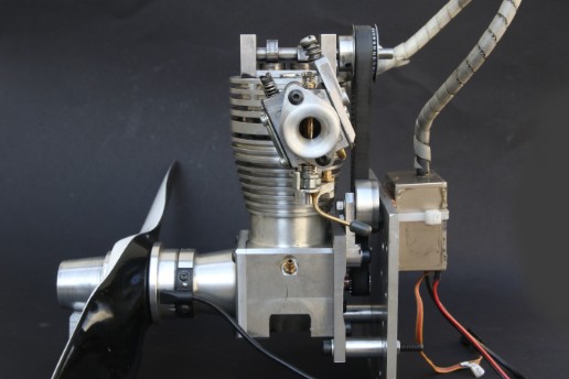
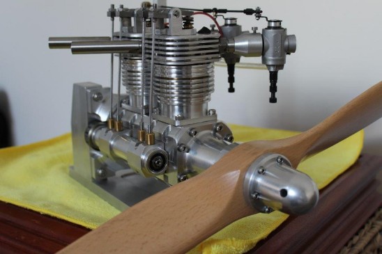
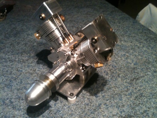
Here are some photos and 2 videos of the single-cylinder four-stroke engine made by Mr. Bruno Engert from Switzerland. The engine was made one size larger, so that the displacement increased to 27 cc.
Mr. Engert writes: "Looking for a quick new project (under 40 working hours) and the knowledge of already having a ready-to-use self-cast piston with a piston ring made of good piston material (i.e. at least 17% silicon content and a diameter of 35 mm ) and a suitable carburettor (Walbro WT 962), the decision was made to use the 17cc 4-stroke engine offered by CAD+Modelltechnik Jung. The criteria, as mentioned, were to use the existing one and run it with gasoline.
I build engines to run them, so functionality comes before aesthetics. The original construction plans were modified 1:1.18, the cylinder head was redesigned with 6 instead of 4 screws, the crankshaft was made completely oil-tight with sealing rings together with the housing covers (already original with O-rings). Fan nipples designed so that the engine in the crankcase can run with 2-3ccm oil. This means that the oil in petrol can easily be reduced to 2%. I've never run an engine in before: either it's good and if the engine gets better with running time, that's a sign that not everything is as it should be (piston clearance / round, matching piston rings, etc.).
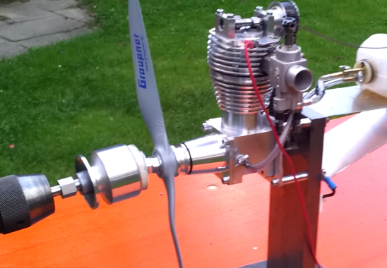
From the start, my home build was power-wise with the 2 new 30cc engines I purchased. After I modified/adjusted a second improved camshaft and the opening point of the valves, with its "only" 27ccm it is even superior to the other two engines!"
The second video shows the mentioned, very interesting comparison test of the three engines "NGH GF 30", the "OS GF30II" and the self-built engine with only 27 cc. The same propeller (Biela, 18 x 6 inches) is mounted on all three engines. The self-made motor rotates the highest and therefore has the highest performance!
Attached are some photos of the V8 engine with reduction gear (capacity 165 ccm), manufactured by trainees at Franz H. Bruder GmbH.
The head of training, Mr. Huber, writes: "After some tinkering, we were able to put the engine into operation. It was a real challenge, but everyone involved had a lot of fun."
The result with the photos shown alongside and the video of the running V8 speaks for itself!
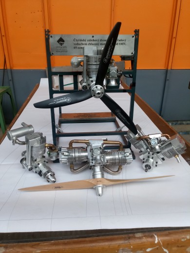
Attached are some photos of several engines built by Mr. František from the Czech Republic:
The 1-cylinder four-stroke engine, the 2-cylinder boxer engine, the 2-cylinder V engine and the 2-cylinder in-line engine were manufactured. All the engines shown alongside were manufactured at the school VOŠ a SPŠ Žďár nad Sázavou.
The engines were modified in such a way that they work with a closed valve train. In addition, all petrol engines are equipped with Walbro carburetors and high-voltage ignition systems
Mr. František writes about the construction and use of the perfectly manufactured engines:
"I'm an airplane model maker, but I only fly fixed wing aircraft. I've tried flying helicopters before, but I've gone back to fixed wing aircraft. It just suits me better.
The in-line and single-cylinder engines are on the shelf as functional teaching aids. I would like to use the boxer engine in the DHC-2 BEAVER with a wingspan of 2.8 m. I also liked the finished V-engine for a Fieseler 156 Storch in 1st scale :4. The biggest adjustments have been made to the cylinder heads. The intake and exhaust ducts have been modified and are axisymmetric in order to simplify production. Another modification is to increase the diameter of the cylinder to 36 mm, thus increasing displacement to 34.5 cc per cylinder. I use roller bearings on the connecting rods. The carburetors are used Walbro carburetors for the DLE 20 engine. I use spark plugs with M 10x1 thread from chainsaws. For the ignition, I also use ignition systems from DLE model engines. In order to achieve good sound insulation, I use 2-chamber silencers of my own manufacture and design, which are welded from an Al alloy."
Attached are some photos of the 6-cylinder compressed air radial engine, manufactured by Mr. L. Krüger.
Mr. Krüger writes: "After a somewhat longer break, I was finally able to complete my compressed air radial engine. Many thanks for the great blueprint, the production was really fun. Everything was described very well. I look forward to the next model based on your plans !"
Nothing more needs to be said :-)
Here are some photos and a YouTube video of the 2-cylinder in-line engine in one of the first test runs, made by Steven Gould (England). Mr. Gould made the engine in about 4 months. Great result!
Mr. Gould continues to write about the construction of the engine:
"The Youtube video was my video posted over a year or so ago. It has created quite a bit of interest.
The construction was very straight forward, the plans were well laid out but as with most engines, the parts needed some minor adjustments to enable a good fit. The cylinder head drawings need a lot more study and careful machining. Cutting the cylinder head cooling fins was difficult as there was limited material between screw holes and exhaust ports and some skill is needed to prevent fins being damaged. The crankshaft required careful alignment when drilling as it would be easy to mis-align this assembly when pressing together. Otherwise, the crankcases, cylinders and pistons were very easy to make. The engine runs well but glow plug ignition is not great. If this engine were to be run frequently, I would use the more reliable CDI spark ignition and two-stroke fuel mix. Glow plugs do not run consistently well in these engines model engine and CDI units are easy to find through Hobby King or similar outlets. It would be easy to design a CDI magnetic pick up assembly at the rear crankshaft cam drive or, less good looking, at the front of the engine.
Otherwise I enjoyed machining this engine and will let you know when I complete the Jung four cylinder flat 4 that is very near completed."
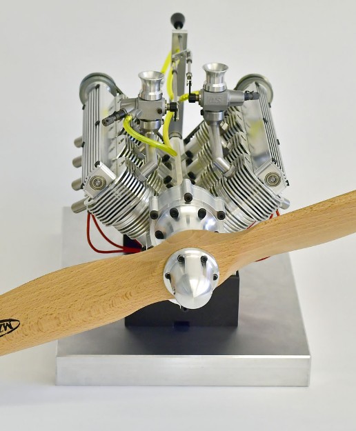
Here are some photos and two videos of the V2 engine made by Bruno Engert from Switzerland. Mr. Engert made two engines of it and completed the first engine in less than a month. It took around 120 hours to do this, including the manufacture of the necessary devices and special tools. Mr. Engert writes: "I bought all parts such as ball bearings and timing belts / wheels in duplicate and will then build a second motor with the experience gained from this motor. A few things can be improved even though the plans have no errors. Some will be purely cosmetic, other things will make sense. But first he has to get his own carburetor and I will build two of them right away. I can copy the new 15 cc OS-Max engine with which he is running at the moment a special feeling when the work and time spent pays off! "
The result is really impressive. The engine with the black anodized cylinders and the red prop spinner is really a feast for the eyes!
The second video with a running time of more than 30 minutes is a very extensive video, put together and very entertaining also presented by Mr. Engert. In addition to various test runs of the two motors, examples show how the parts required to build the motor can be manufactured as simply as possible.
There are really some smart ideas here. The video is therefore recommended for the layperson to the expert.
Here is a YouTube video of the 2-cylinder boxer engine during the first test run on a test bench, manufactured by apprentices from the Poma company.
Enclosed photos of the V6 engine with 100 cc, here in a water-cooled version, for driving in a model racing boat. Lutz Höhne sent us the photos and made the corresponding modifications on our own.
Here are some photos of the V8 engine under construction with 165 cc and flanged reduction gear, made by Karl-Heinz Hackländer.
On the left are some photos of the single-cylinder four-stroke engine with a displacement of 17.5 cc, manufactured by Willy Wierichs according to our construction plan.
On the left is a photo of the V2 engine, made by Eric Dusart from France. The engine is almost finished, only the exhaust and intake pipes with the carburetor are missing. Contrary to our construction plan, the engine was provided with a closed valve train, which also fits the engine very well.
Alongside are some photos of the 4-cylinder boxer engine from Rudolf Hahn in Austria. Mr. Hahn made some changes in the construction of the engine. The engine is equipped with an ignition system so that the engine can run on petrol (petrol / oil mixture). The ignition distributor is also built by Mr. Hahn and is mechanically driven by the camshaft. The ignition distributor has the advantage that a simple and cheaper ignition system can be used for a single-cylinder engine. A Walbro carburettor is used as the carburettor, which is supplied with fuel by means of an electric petrol pump.
As you can see, the effort for the conversion is relatively high. The advantage, however, is that you can use the cheaper petrol / oil mixture from the petrol station. The engine also runs more reliably and safely than in glow ignition mode.
The engine has now undergone several successful test runs on a test bench. As you can see on the YouTube video, the motor starts reliably with a minimal handshake.
Mr. Hahn writes: "The engine starts very easily by hand. The construction of the engine is a bit complex, but with this engine sound you are rewarded sufficiently. You can say the engine sound is in no way inferior to the Moki radial engine sound! The engine turns a 28x10 inch propeller with 5000 rpm. But I will try a 26x14 inch later. "
The adjacent YouTube video shows the boxer engine during one of the first test runs.
Here are some photos of the 4-cylinder boxer engine from Geoff Haydt from Canada. Within 7 months, Mr. Haydt built the engine with a few minor changes, as Mr. Haydt writes, but not from technical reasons. Necessity, but rather to experiment and give the engine its own touch. The result is impressive! The engine is still running as a glow starter with model engine fuel, but is to be converted to gasoline and ignition in the future.
Enclosed the link to the English language forum "Home model engine machinist" (http://www.homemodelenginemachinist.com)
Here, Mr. Haydt's engine was presented as part of the "Project of the Month". In addition to additional photos, there are also some videos of the engine running.
On the left are some photos of Frank Schreiner's V8 engine. The V8 engine and the 9-cylinder radial engine are the two absolute highlights from our construction series of model engines.
The now completed V8 engine with integrated reduction gear was built by Mr. Schreiner with some modifications and is to be installed in a P51 Mustang with a wingspan of 2.5 m in the future. The following changes were made:
In addition to the increased displacement to 165 cc and a modified crankshaft with a changed ignition sequence, an additional reduction gear was installed to drive a 4-blade propeller. The reduction gear designed with a reduction of approx.1.4 drives a propeller with a 29 inch diameter (approx. 74 cm!). In order to install a normal left-handed propeller, it was necessary for the engine to turn clockwise without the gearbox. Mr. Schreiner solved this simply by "wrongly" mounted cylinders and cylinder heads. I.e. the cylinders / cylinder heads normally arranged on the left are mounted on the right and vice versa. The engine runs the other way around and the exhaust pipes could be made extremely short and straight. As a result, the V8 fits perfectly under the hood of the P51 Mustang.
The photos show the engine in different views. The first two photos show the engine diagonally from the front. You can see the additionally installed reduction gear for driving the large 4-blade propeller. A photo shows the engine diagonally from behind. Here you can see the toothed belt drive of the two camshafts.
In addition, the camshaft grinding machine for grinding the 8 camshafts.
The video opposite shows the Video shows the V8 engine from Mr. Schreiner during one of the first test runs on a test bench. One can only say that the sound of the V8 engine is simply absolutely amazing!
Enclosed is a photo and a YouTube video of the 1-cylinder four-stroke engine manufactured by Patrick Kusser according to our construction plan. The engine is mounted on a test bench for testing and runs really well.
Currently a photo sent in by Stephan Reuter. The photo shows Mr. Stephan Reuter's journeyman's piece in the form of the 2-cylinder boxer engine, manufactured according to our construction plans. All you can say is congratulations for this perfectly manufactured engine.
On the right are some photos from Omid Fardin (also from Switzerland) of the V8 engine that has almost been completed. In addition to the propeller driver and some small parts, only the 4 carburettors are missing. Then nothing should stand in the way of the first start of the engine. The whole thing looks really clean and perfect!
The engine is completely made according to the drawings for our V8 engine with 132 ccm.
Four of the 2-cylinder boxer engines were created as apprentice projects at Armbruster. Almost all parts were manufactured on conventional metalworking machines to learn the precise manufacture of the individual parts up to the assembly of the motors. The result is impressive. After completion, all engines were tested on a test bench.
One of the photos shows one of the finished 2-cylinder boxer engines on the test bench. A 22/10 "wood propeller from Menz with a diameter of 56 cm x 25.4 cm pitch is installed.
As can be seen in the video opposite, the motors can be easily adjusted by hand using so-called. Start the ripcord. The video shows the boxer engine during one of the first test runs.
On the left, we have received some photos from Gerhard Müller (Switzerland) about the construction of the 8-cylinder V engine, which we naturally do not want to withhold from you.
Mr. Müller writes: "Here are some photos of your super engineering achievement (Bravo). I'm really curious to see how it sounds. It was great fun, a challenge and thinking is required. I learned a lot as an almost retired man. I have I learned toolmaking at the time and I have old conventional machines and your blueprint for the V8 engine with 132 cc. A fantastic thing that really caused me some difficulties, but now everything is ready for the final assembly. Thank you for your plans. "
The first photo gives an idea of how many individual parts this V8 engine consists of. The other photo shows an image section with the cylinder heads and the cylinders with the pistons and connecting rods. One can only say: first-class performance!
At the moment, Mr. Müller is busy assembling the V8 engine. After its completion, further pictures will be published here.
On the left are some photos by Jørgen Hald (Denmark) about the construction of the 2-cylinder boxer engines, which we naturally do not want to withhold from you.
Mr. Hald built two of the boxer engines. He writes: "... here are some pictures of the two engines that I made according to your drawings. One of them consists of a crankshaft, connecting rods and pistons from an old two-stroke engine, all other parts are made according to your drawing completely made according to the drawings ". In the meantime, the first test runs of the two engines have also been successful, reports Mr. Hald.
At the moment, Mr. Hald is already working on the next project, namely the production of the 5-cylinder radial engine.
Mr. Bösch sent us some pictures of the now completed 1-cylinder four-stroke engine from our series of blueprints. One can only say about the pictures: an absolutely perfect execution down to the last detail!
Mr. Bösch is head of the mechanical workshop at the Physics Institute at the Albert-Ludwigs University in Freiburg.
Rudolf Hahn currently sent us these two pictures of the V2 engine, as of June 2006.
Mr. Hahn reports that he immediately started building parts for 2 engines because he expected rejects because of his simple milling machine. However, the fears were unfounded, so that he was now able to complete two engines.
His interesting comment on the construction of the engine: "... the question arises why you do such a thing to start such a project. In my circle of acquaintances there were comments such as the highest admiration to spinning that does not work. I say myself building such an engine is one of the last adventures of our time. "
The construction period lasted from November 2005 to June 2006 with breaks. The engine has already passed its first test run with flying colors. Mounted on a test bench, it was able to demonstrate its performance. Mr. Hahn writes: "The engine has been running for a total of 20 minutes. The running-in must be carried out very carefully, since the internal friction ensures a rapid rise in temperature (always allow it to cool well). After the first 10 minutes of running, the engine suddenly improved. I never actually expected the engine to run so well."
Christian Doblinger sent us this view of the 1-cylinder four-stroke engine with 17.5 ccm he had made according to our construction plan.
Michael Krüger is currently working on the 2-cylinder V-engine with 35 cc from our range of construction plans. In this regard, Mr. Krüger: "The two has not yet progressed so far." But should "lift" a plane from a friend in the air next season. Unfortunately, my engines all dust in the basement, since I am not a model plane myself and I do not know anyone who does so builds big airplanes to need such "aggregates". "
In the photo you can already see the completed multi-part crankshaft, parts of the crankcase and the two cylinders.
Matthias Niebling made this CNC milling machine according to our construction plan. A milling head from Wabeco was installed. Floor space of the machine approx.1,200x800 mm. Travel paths of the milling machine (x / y / z) approx. 745 x 275 x 100 mm.
Karl Dindorf made this 4-cylinder boxer engine. Here during one of the first test runs of the engine, with the flywheel installed. Mr. Dindorf made the engine completely according to the drawings. The only modification is the single carburetor with intake manifold instead of double carburetor.
Peter Krauss sent us these pictures of the 1-cylinder four-stroke engine he had made and the 5-cylinder radial engine currently under construction. Mr. Krauss produced the 1-cylinder engine in duplicate with different additional equipment.
Enclosed is a picture of the 4-cylinder boxer engine mounted on a stand construction, made by the author of this website Volker Jung.
Reprint only with the permission of the author. All statements without guarantee.
Note on all links on these pages:
With judgment of May 12th, 1998 - 312 O 85/98 - "Liability for links" the regional court Hamburg decided that the operator of a homepage has to take responsibility for the contents of the linked page. According to the court, this can only be prevented by expressly distancing yourself from this content.
We as CAD+Modelltechnik Jung expressly distance ourselves from all content on all linked sites and do not adopt their content as our own. This declaration applies to all available links on the pages of this web portal.